Home / Projects / electronic lock suggestion box
electronic lock suggestion box
500 Reviews
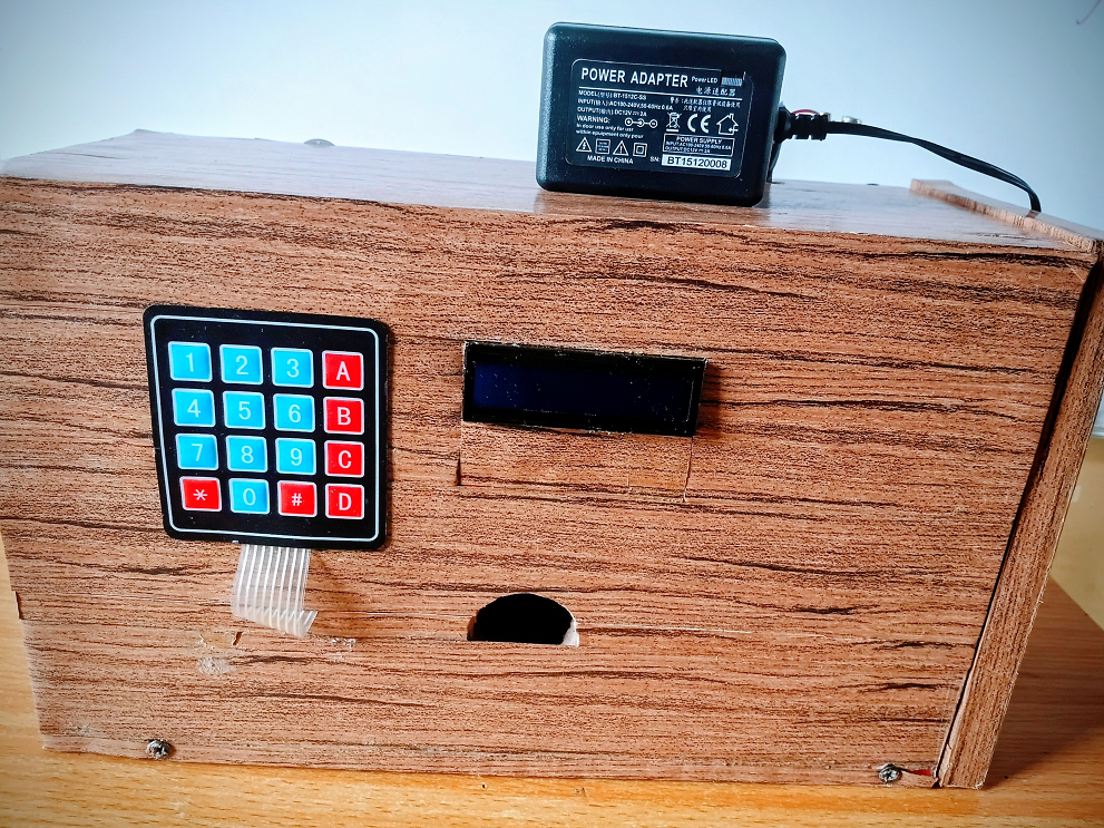
This project shows you how to make an electronic lock suggestion box that securely collects feedback by allowing only authorized access through a digital, programmable locking system.
N40,860.00
-Products


Inexpensive Membrane Matrix Keypads
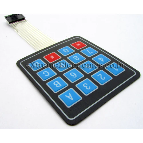
The keypad we will be using in our experiments is very inexpensive and easily available. It consists of four rows and four columns, each connected to a film ribbon cable.
The film ribbon cables both terminate with an 8-pin female Dupont connector. The pinouts are as follows:
1.Row 1 2.Row 2 3.Row 3 4.Row 4 5.Column 1 6.Column 2 7.Column 3 8.Column 4 If you obtain a 4 x 3 keypad you can use it in the experiments, the only difference is that it will have a 7-pin connector and will be missing the Column 4 connection.
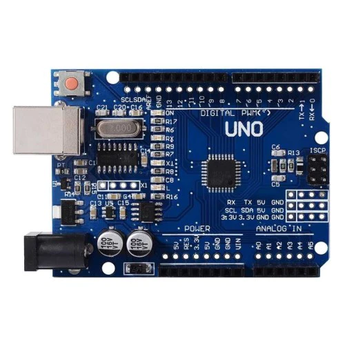
Now that you understand how the keypad works let’s see how to use it with an Arduino.
Basic Keypad Test The first experiment we’ll perform with the keypad is to simply connect it up to the Arduino and use the serial monitor to verify that we can read all of the keys. This is a good way to get to know how to work with the keypad, and can also be used to verify that all of the keys are indeed working.
Keypad Test Hookup The hookup of the keypad and the Arduino is shown below:
9 - r1
8 - r2
7 - r3
6 - r4
5 - c1
4 - c2
3 - c3
2 - c4
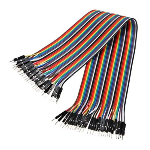
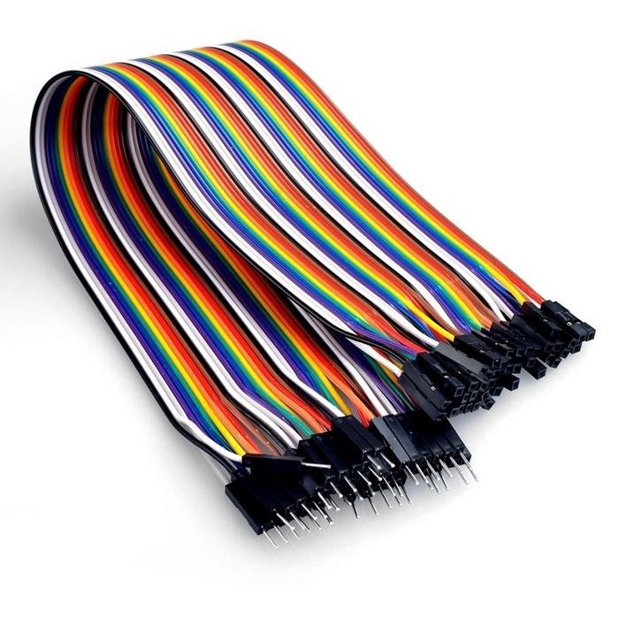
The easiest way to get everything connected is to use a multi-conductor male-to-male Dupont ribbon cable with 8 conductors. The hookup is quite simple, as the Arduino connections are all made in the same order as they are on the keypad connector.
Once everything is hooked up you can proceed to the sketch that we’ll use to test our keypad.
Keypad Test Sketch
The sketch we’ll be using is simplified by the use of a special library, the Keypad Library by Mark Stanley and Alexander Brevig. With this library using matrix keypads is very easy.
You can install this library directly from your Library Manager.
-Open your Arduino IDE.
-Select the Sketch item from the top menu bar.
-Navigate to Include Library. A sub-menu will open.
--Select Manage Libraries. This will open the Library Manager dialog box.
In the Filter Your Search box type “keypad”.
-From the results scroll down until you find the Keypad by Mark Stanley and Alexander Brevig library.
-Select Install to install the library
-Close the Library Manager dialog box.
Once you have this library installed you can enter the following sketch:
Matrix Keypad Demo keypad-demo.ino Demonstrates use of 4x4 matrix membrane keypad with Arduino Results on serial monitor
DroneBot Workshop 2020 https://dronebotworkshop.com */
// Include the Keypad library #include <Keypad.h>
// Constants for row and column sizes const byte ROWS = 4; const byte COLS = 4;
// Array to represent keys on keypad char hexaKeys[ROWS][COLS] = { {'1', '2', '3', 'A'}, {'4', '5', '6', 'B'}, {'7', '8', '9', 'C'}, {'*', '0', '#', 'D'} };
// Connections to Arduino byte rowPins[ROWS] = {9, 8, 7, 6}; byte colPins[COLS] = {5, 4, 3, 2};
// Create keypad object Keypad customKeypad = Keypad(makeKeymap(hexaKeys), rowPins, colPins, ROWS, COLS);
void setup() { // Setup serial monitor Serial.begin(9600); }
void loop() { // Get key value if pressed char customKey = customKeypad.getKey();
if (customKey) { // Print key value to serial monitor Serial.println(customKey); } }
The code for this sketch is very simple. The main thing to note is how the keypad library requires its input parameters in an array format.
After including the Keypad library we define a couple of constants for the number of rows and columns in our keypad. If you are using a different keypad then modify these parameters accordingly.
Next, we create an array that represents the rows and columns of the keypad. The elements of the array define the values of each key.
Finally, we define a couple more arrays. These arrays specify the Arduino connections to the row and column pins on the keypad.
We use all of the above arrays with the Keypad library to create an object that represents our keypad.
In the Setup, we just need to start the serial monitor.
The Loop is very simple. We use the getKey method of the keypad library to get a key value when it detects a keypress. Then we simply print that to the serial monitor.
Load the sketch and open your serial monitor, making sure to observe the baud rate (it should be 9600 baud). Now press some keys on the keypad. You should observe the key values displayed on the serial monitor.
Keypad with LCD
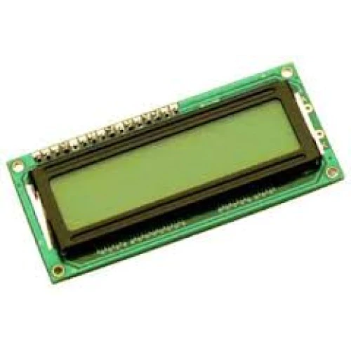
Our next experiment is just an extension of the first one. This time we will use an LCD display instead of the serial monitor to read keypress values.
Using a display such as an LCD or OLED display with the keypad is a very common application, as it can give you feedback when you are entering data.
LCD Hookup
To reduce the number of connections required we will be using an LCD display with an I2C backpack. This makes the hookup extremely simple, as illustrated below:
ARDUINO UNO LCD DISPLAY
  5V               5V

  GND              GND

  A4               SDA

  A5               SCL
Once you have it all connected we can modify our sketch to use the LCD.
LCD Sketch
Once again we will be making use of a library to simplify our coding. Unlike the previous library, however, this one is not available in the Library Manager.
The LiquidCrystal_I2C Library is specifically meant for driving LCD displays that use the I2C backpack. You can download this from GitHub as a ZIP file.
Once you have the ZIP file downloaded you’ll need to install the library.
Open the Arduino IDE.
-Select Sketch from the top menu
-Scroll down and highlight Include Library. A sub-menu will open.
-Select Add ZIP Library. This will open a file dialog box.
-Use the dialog box to navigate to the ZIP file you downloaded and select it.
-Click OK to install the library.
Now that you have the library let’s take a look at our modified sketch.
Matrix Keypad with LCD Display Demo keypad-demo-lcd.ino Demonstrates use of 4x4 matrix membrane keypad with Arduino Results on LCD Display Display uses I2C backpack
*/
// Include Arduino Wire library for I2C #include <Wire.h> // Include LCD display library for I2C #include <LiquidCrystal_I2C.h> // Include Keypad library #include <Keypad.h>
// Constants for row and column sizes const byte ROWS = 4; const byte COLS = 4;
// Array to represent keys on keypad char hexaKeys[ROWS][COLS] = { {'1', '2', '3', 'A'}, {'4', '5', '6', 'B'}, {'7', '8', '9', 'C'}, {'*', '0', '#', 'D'} };
// Connections to Arduino byte rowPins[ROWS] = {9, 8, 7, 6}; byte colPins[COLS] = {5, 4, 3, 2};
// Create keypad object Keypad customKeypad = Keypad(makeKeymap(hexaKeys), rowPins, colPins, ROWS, COLS);
// Create LCD object LiquidCrystal_I2C lcd(0x3F, 16, 2);
void setup(){ // Setup LCD with backlight and initialize lcd.backlight(); lcd.init(); }
void loop(){ // Get key value if pressed char customKey = customKeypad.getKey();
if (customKey){ // Clear LCD display and print character lcd.clear(); lcd.setCursor(0, 0); lcd.print(customKey); } }
A quick look at the code confirms what you probably already suspected – this sketch is virtually identical to the last sketch!
One difference, of course, is that we are including both the Wire Library for I2C and the new LiquidCrystal_I2C library that we just installed. Both of these libraries are required to use the LCD display with the I2C backpack.
In line 39 we create an object to represent our LCD display. The first parameter in the object is “0x3F”, which is the hexadecimal I2C address of the display. If you are using a display that has a different I2C address you will need to modify this parameter accordingly.
In the Setup we initialize the LCD display and also enable its backlight.
The Loop is almost identical to the previous sketch. Once again we get the value of the keypress and hold it in a character variable. Then we clear the LCD display and print the character to the display. It will remain on the display until the next key is pressed.
Load the sketch and observe the display while you press keys. If you don’t see anything try adjusting the brightness control on the I2C backpack.
Now that we have the basics down let’s build something practical with our keypad.
Combination Lock
A great use for a matrix keypad is to build a combination lock. You can use this to lock a door or a drawer or to regulate access to an electronic device.
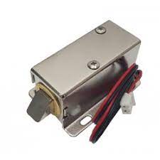
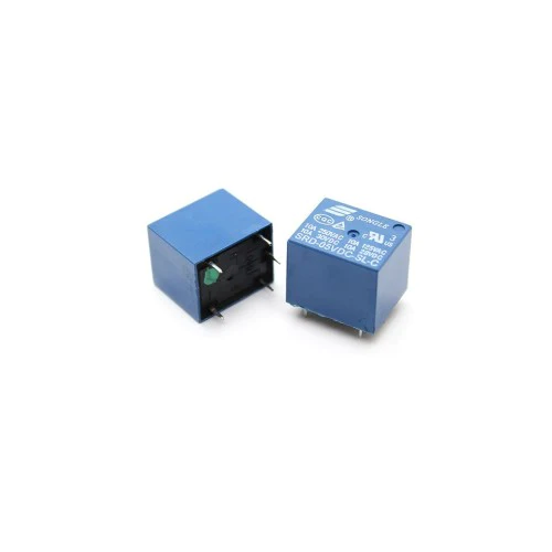
Our lock project will drive a relay, which in turn could be used to activate a standard locking solenoid. These devices stay in the locked position and will only release the lock when voltage is applied to them. Typically these devices use 12-volts to operate.
In most cases you’ll only want to apply voltage for a few seconds, just enough time to unlock the solenoid to open the guarded area. Applying voltage to the solenoid for too long a period can burn it out, you should read the specifications on your locking mechanism for more details.
Our lock will operate as follows:
The LCD display will prompt the user to enter a password As the password is entered it will be printed on the display When the correct number of characters have been entered the code will check the data against the stored combination. If the code is correct it will activate the relay for five seconds. If the code is incorrect it will display an error message. It will then clear the display. Let’s get working on it!
Combination Lock Hookup
All that we need to do to create our lock is to add a relay module to the existing LCD hookup
Relay modules typically have three input connections:
-Ground
-Power (typically 5-volts)
-Trigger or Input
The output of the relay is labeled as follows:
-NC (normally closed)
-Common
-NO (normally open)
Typically you would connect one side of your solenoid (or other activated device) to one side of the power supply (i.e. 12-volts). The other side would be routed between the Common and NO connections of the relay. This way the relay will switch the solenoid on when it is activated.
After wiring it up it’s time to turn our attention to the sketch that will run our combination lock.
SUGGESTION BOX SKETCH
Here is the code for our suggestion box:
Matrix Keypad Combination Lock Demo keypad-demo-lock.ino Combination lock using 4x4 matrix membrane keypad with Arduino Results on LCD display Drives relay
*/
// Include Arduino Wire library for I2C #include <Wire.h> // Include LCD display library for I2C #include <LiquidCrystal_I2C.h> // Include Keypad library #include <Keypad.h>
// Length of password + 1 for null character #define Password_Length 8 // Character to hold password input char Data[Password_Length]; // Password char Master[Password_Length] = "123A456";
// Pin connected to lock relay input int lockOutput = 13;
// Counter for character entries byte data_count = 0;
// Character to hold key input char customKey;
// Constants for row and column sizes const byte ROWS = 4; const byte COLS = 4;
// Array to represent keys on keypad char hexaKeys[ROWS][COLS] = { {'1', '2', '3', 'A'}, {'4', '5', '6', 'B'}, {'7', '8', '9', 'C'}, {'*', '0', '#', 'D'} };
// Connections to Arduino byte rowPins[ROWS] = {9, 8, 7, 6}; byte colPins[COLS] = {5, 4, 3, 2};
// Create keypad object Keypad customKeypad = Keypad(makeKeymap(hexaKeys), rowPins, colPins, ROWS, COLS);
// Create LCD object LiquidCrystal_I2C lcd(0x3F, 16, 2);
void setup() { // Setup LCD with backlight and initialize lcd.backlight(); lcd.init();
// Set lockOutput as an OUTPUT pin pinMode(lockOutput, OUTPUT); }
void loop() {
// Initialize LCD and print lcd.setCursor(0, 0); lcd.print("Enter Password:");
// Look for keypress customKey = customKeypad.getKey(); if (customKey) { // Enter keypress into array and increment counter Data[data_count] = customKey; lcd.setCursor(data_count, 1); lcd.print(Data[data_count]); data_count++; }
// See if we have reached the password length if (data_count == Password_Length - 1) { lcd.clear();
if (!strcmp(Data, Master)) {
  // Password is correct
  lcd.print("Correct");
  // Turn on relay for 5 seconds
  digitalWrite(lockOutput, HIGH);
  delay(5000);
  digitalWrite(lockOutput, LOW);
}
else {
  // Password is incorrect
  lcd.print("Incorrect");
  delay(1000);
}

// Clear data and LCD display
lcd.clear();
clearData();
} }
void clearData() { // Go through array and clear data while (data_count != 0) { Data[data_count--] = 0; } return; }
You’ll note that it uses the same libraries as the LCD sketch, which of course makes perfect sense.
We define the length of the password on line 23. Note that this also includes a null character, so the value here is actually one more than the actual password length. You can change this to make an easier or harder password.
Two character variable arrays are defined. The Data array holds the key entries, and the Master arry has the actual password. You should edit the password to be something harder to guess than just the first seven digits on the keypad!
We also define the lock output pin. I used pin 13, as the Arduino has a built-in LED on that pin, so it can be used for troubleshooting if the relay fails to activate.
The byte_count variable counts the number of keypresses entered.
In the Setup we define pin 13 as an OUTPUT.
We start the Loop by placing the LCD cursor in the top left corner and printing “Enter Password:”. Then we look for a keypress, as we did in the previous sketches.
If we get a keypress we record the value in an element of the Data array. We then increment the counter for the next keypress.
After that we check to see if we have enough characters. If we don’t we end the Loop and repeat until we do.
Once we have enough characters we compare the Data array to the Master array. If the arrays are identical then we have the correct password and we activate the relay for 5 seconds. If it is incorrect we print “Incorrect” on the display and hold it there for a second.
In both cases we then clear the display and call the clearData function to clean out the Data array.
Reviews(10)
5.0
66%
4.0
33%
3.0
16%
2.0
8%
1.0
6%
No reviews yet. Be the first to add a review!